Semester 3 - Computer Networks - Important Topics Part 1
Network Protocols
-
These are rules for how devices communicate over a network. They’re used in both software and hardware.
-
Network Communications Protocols: Allow devices to communicate over networks.(e.g., IP, TCP, HTTP)
-
Network Security Protocols: Secure data for authentication, integrity, and encryption. (e.g., SSH, SSL, TLS).
-
Routing Protocols: Help routers exchange route information and select the best path. (e.g., OSPF, BGP)
-
Service Discovery Protocols: Used for automatic detection of devices or services. (eg DHCP for IP address allocation, DNS for name-to-IP address translation)
-
-
Network Protocol Functions: These protocols perform specific functions necessary for communication.
-
Addressing: Identifies sender and receiver of the message. (e.g., Ethernet, IPv4, IPv6)
-
Reliability: Provides guaranteed delivery if messages are lost or corrupted. (e.g., TCP)
-
Flow control: Ensures efficient data flow between two devices. Also provided by TCP. (e.g., TCP)
-
Sequencing: Labels each transmitted segment of data for correct reassembly. Useful if data is lost or received out-of-order. (e.g., TCP)
-
Error Detection: Determines if data was corrupted during transmission. (e.g., Ethernet, IPv4, IPv6, TCP)
-
Application Interface: Contains information for process-to-process communications between network applications. HTTP or HTTPS are used for accessing a web page. (e.g., HTTP, HTTPS)
-
-
Protocol Interaction: A message sent over a network typically requires several protocols, each with its own function.
-
HTTP: Governs how a web server and client interact. Defines content and formatting of requests and responses.
-
TCP: Manages conversations, guarantees reliable information delivery and manages flow control.
-
IP: Delivers messages from sender to receiver. Used by routers to forward messages across networks.
-
Ethernet: Delivers messages within the same Ethernet local area network (LAN).
-
Models
- OSI and TCP/IP models help understand network concepts.
- They ensure different vendor products can work together.
- OSI model is great for explaining network concepts and troubleshooting.
- TCP/IP suite protocols are the current standards for networks.
- It’s key to understand both models and how they relate.
- Usually, when discussing layers, we refer to the OSI model.
- When discussing protocols, we typically refer to the TCP/IP model.
OSI
-
The OSI (Open Systems Interconnection) model is a conceptual framework used to understand and describe how different network protocols interact and work together to provide network services.
-
The OSI model consists of seven different layers described below.
| OSI Model Layer | Description |
|---|---|
| 7 - Application | Where network-aware applications, such as web browsers or email clients, interact with the network. |
| 6 - Presentation | Translates the data format for the application, like converting text files from one code page to another, or encrypting and decrypting data. |
| 5 - Session | Establishes, manages, and terminates ‘conversations’ between networked applications. |
| 4 - Transport | Ensures data gets to the correct application at the destination and checks that all data has arrived. |
| 3 - Network | Determines the best path for data to take through the network from source to destination. |
| 2 - Data Link | Controls how data is sent to and received from the network, including error checking and correction. |
| 1 - Physical | Handles the physical transmission of data, including the network cabling and electrical signals. |
TCP/IP
- TCP/IP stands for Transmission Control Protocol/Internet Protocol.
- TCP/IP is the communication protocol for connecting network devices on the internet.
- It’s an open standard, meaning no single company controls it.
- Unlike OSI, it was developed from real network implementations, making it the basis for the modern internet.
- The TCP/IP model has four key functional areas, each crucial for successful communication.
| TCP/IP Layer | Function | Example Protocols |
|---|---|---|
| Application | Represents data to the user and controls dialogue | DNS, Telnet, SMTP, POP3, IMAP, DHCP, HTTP, FTP, SNMP |
| Transport | Supports communication between diverse devices across diverse networks | TCP, UDP |
| Internet | Determines the best path through the network | IP, ARP, ICMP |
| Network Access | Controls the hardware devices and media that make up the network | Ethernet, Wireless |
Comparision - OSI vs TCP/IP
| OSI model | TCP/IP model | Protocol data unit (PDU) | Example | Equipment operating on given layer | Domain |
|---|---|---|---|---|---|
| Application | Application | Data | HTTP, FTP, SMTP, DNS | Firewall, Load Balancer | - |
| Presentation | - | - | ASCII, JPEG, MPEG | - | - |
| Session | - | - | NetBIOS, SAP | - | - |
| Transport | Transport | Segment | TCP, UDP | Router w/NAT, Firewall | - |
| Network | Network | Packet | IP, ICMP | Router | Subnet |
| Data-link | Data-link | Frame | Ethernet, 802.11 | Switch | Broadcast domain |
| Physical | Physical | Bit/Symbol | UTP, Single-mode fiber, Multi-mode fiber | Hub, Repeater | Collision domain |
Physical Layer
Characteristics
- Physical Layer Standards
- Developed by various organizations such as ISO, TIA/EIA, ITU, ANSI, IEEE.
- Standards govern hardware components like electronic circuitry, media, connectors.
- Physical Components
- Examples: NICs, interfaces, connectors, cable materials.
- Transmit signals representing bits.
- Cisco 1941 router ports and interfaces are physical components specified by standards.
- Encoding
- Examples: Manchester encoding, 4B/5B encoding, 8B/10B encoding.
- Converts data bits into predefined code or pattern.
- Enables recognition of data by sender and receiver.
- Signaling
- Examples: Electrical, optical, or wireless signals.
- Represents “1” and “0” on the media.
- Signal types defined by standards (e.g., voltage levels, pulse durations).
- Bandwidth
- Refers to data capacity of a medium.
- Examples: kbps, Mbps, Gbps.
- Determined by physical media properties and signaling technologies.
Network Media Forms and Standards
Three basic forms of network media exist:
-
Copper cable: The signals are patterns of electrical pulses.
-
Fiber-optic cable: The signals are patterns of light.
-
Wireless: The signals are patterns of microwave transmissions.
- Copper Cabling:
- Characteristics: Copper cabling is affordable and easy to install for network connections.
- Types: Unshielded twisted-pair (UTP) and shielded twisted-pair (STP) cables.
-
Example: Ethernet cables commonly use UTP for connecting devices.
- UTP Cabling: (optional)
- Properties: UTP cables are flexible, cost-effective, and use RJ-45 connectors.
- Standards and Connectors: TIA/EIA-568 standards define wiring schemes. RJ-45 connectors terminate UTP cables.
- Example: Straight-through cables connect different devices (e.g., computer to switch), while crossover cables connect similar devices (e.g., computer to computer).
- Fiber-Optic Cabling:
- Characteristics: Fiber-optic cables use light for high-speed and long-distance data transmission.
- Types: Single-mode fiber (SMF) for long distances and multimode fiber (MMF) for shorter distances.
- Example: Fiber-optic cables are commonly used in high-speed networks and long-distance communication.
- Wireless Media:
- Characteristics: Wireless media allows data transmission without cables, providing mobility.
- Types: Wi-Fi for local area networks, cellular networks for wider coverage.
- Example: Wireless LANs use Wi-Fi and access points for wireless device connectivity.
| Media | Physical Components | Frame Encoding Technique | Signaling Methods |
|---|---|---|---|
| Copper cable | UTP | Manchester encoding | Changes in the electromagnetic field. |
| Coaxial | Nonreturn to zero (NRZ) | Intensity of the electromagnetic field. | |
| 4B/5B codes with MLT-3 signaling | Phase of the electromagnetic wave. | ||
| Fiber-optic cable | Single-mode fiber | PAM5 | Pulses of light |
| Multimode fiber | 8B/10B | Wavelength multiplexing using different colors | |
| Wireless | Access points | Direct Sequence Spread Spectrum (DSSS) | Radio waves |
| NICs | Orthogonal Frequency Division Multiplexing (OFDM) | ||
| Radio | |||
| Antennas |
Data Link Layer Overview
The Data Link Layer is the second layer in the OSI model, and it consists of two sub-layers:
- Logical Link Control (LLC) sub-layer: Handles error correction, flow regulation, data framing, and addressing within the MAC sub-layer.
- Media Access Control (MAC) sub-layer: Manages access to shared media, such as Token passing or Ethernet.
Key Functions of Data Link Layer :
- Framing: Transforms bit streams from the network layer into manageable frames.
- Physical Addressing: Inserts a header for identifying sender/receiver addresses when routing frames.
- Flow Control: Balances sender/receiver transmission rates, preventing receiver congestion.
- Error Control: Adds a trailer to frames for accuracy and avoidance of frame duplication.
- Access Control: Determines which device controls the link when multiple devices are connected.
Data Link Layer
Data Link Frame
- Data Link Layer wraps data in a ‘frame’ with a header and trailer for local media transport.
- A frame has three parts: Header, Data, Trailer.
- Frame structure can change based on different protocols.
- The type and amount of control information in a frame depend on media and topology needs.
Frame Fields include the following
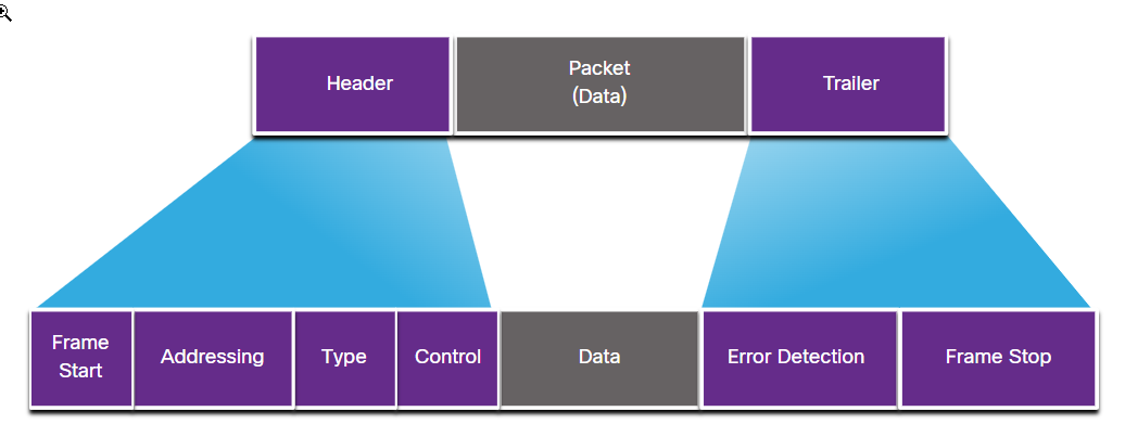
- Start and stop flags: Mark the frame boundaries.
- Addressing: Shows where the frame comes from and where it’s going.
- Type: Tells us the Layer 3 protocol in the data field.
- Control: Points out special flow control services, like QoS.
- Data: The actual information being transported.
- Error Detection: Checks if the frame arrived without mistakes.
Layer 2 Addresses
- Layer 2 uses physical addresses to transport a frame across local media.
- These addresses are unique to each device and don’t show network location.
- Layer 2 addresses work within the same shared media and IP network.
Difference between UDP and TCP
| TCP | UDP | |
|---|---|---|
| Connection | Connection-oriented | Connectionless |
| Suitability | High reliability applications, not critical of transmission delays (e.g., HTTP, HTTPs, FTP, SMTP, Telnet) | Fast, efficient transmission applications (e.g., DNS, DHCP, TFTP, SNMP, RIP, VOIP) |
| Ordering of Data Packets | Rearranges data packets in order | No inherent order; managed by the application layer |
| Speed and Reliability | Slower, but guarantees packet delivery | Faster, but no guarantee of delivery |
| Header Size | 20 bytes | 8 bytes |
| Connection Setup | Requires three packets to set up a socket connection | Lightweight, no connection tracking |
| Flow Control | Handles flow control, reliability, and congestion control | No option for flow control |
| Error Checking | Error checking and recovery present; retransmits erroneous packets | Error checking present, but discards erroneous packets without recovery |
| Handshake | Includes handshake process (SYN, SYN-ACK, ACK) | No handshake (connectionless protocol) |
TCP Handshake Procedure
- SYN (Synchronize): Initiates a connection.
- ACK (Acknowledgment): Acknowledges a received packet or confirms connection establishment.
- FIN : Terminates or closes a connection.
TCP connection establishment (three-way handshake):
- Client sends a TCP segment with a SYN flag
- Server responds with a TCP segment with SYN and ACK flags
- Client responds with a TCP segment with an ACK flag.

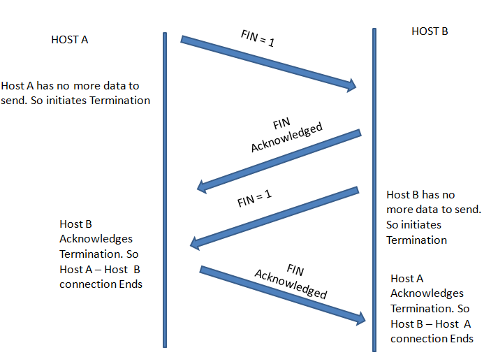
TCP four-way termination sequence
- Host A sends a TCP segment with ACK and FIN flags
- Host B responds with a TCP segment with an ACK flag
- Host B sends a TCP segment with ACK and FIN flags
- Host A responds with a TCP segment with an ACK flag